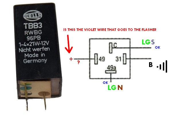
Flasher WiringI cant locate any data on the Hella TBB3 but it is an electronic flasher relay which is not an original fitment. The original is a GFU 2215 which only has two terminals. These original units are often replaced because poor earth connections stop the lights from flashing at the correct speed.
On a UK 81 model the standard flasher connections are as follows:-
LG N (Light Green / Brown) is the feed from the flasher to the indicator switch (which feeds the selected left or right flashers) This goes to terminal 49A on an electronic flasher
LG S (Light Green / Slate ) is the 12v supply from hazard switch to the flasher (it is only energised when the hazard flasher is in the off position) This goes to terminal 49 on an electronic flasher
As you have identified the unit requires an earth connection. This goes to terminal 31 on an electronic flasher
The other terminal may not be used or may be a 12v power supply. I suggest you initially connect it without any wired to the C terminal and see if this works. If it doesn't work, post a message here & I will go through a checking procedure to find out how it works.
Headlamp CBTemporarily for testing the head lamp circuit breaker could be replaced by a fuse, but its a self resetting device so that you don't suddenly lose all your lights when a bulb blows.
Eureka WireThe Eurkea wire is need as the car has a 6v coil but a 12v supply. When starting 12v is sent to the coil to make a big fat spark but when running a resistor in the Eureka wire drops the supply voltage to the coil to 6v to prevent it burning out
New Wiring DiagramWhile my drawing is for an 81 UK model you may find the new wiring diagrams I prepared to be helpful as they separate the circuits into basic blocks and add an explanation of how they work. It can be downloaded from the following link which I posted last year on this site:-
https://drive.google.com/file/d/0B0OCjgNgn85aOEdlYWp6dnFfc2s/viewCheers
Howard (Doha Qatar)


