Anonymous

TR7 connection to Distributor, Coil & Ballast

The all purpose forum for any TR7/8 related topics.
Post Reply
Marsu
Swagester
Posts: 570
Joined: 03 Oct 2009 20:57
Location: Australia
Contact:

TR7 connection to Distributor, Coil & Ballast

Postby Marsu » 25 Sep 2010 21:06

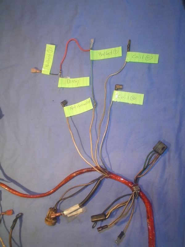
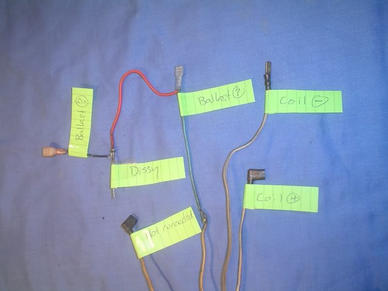
I want to make sure I re-connect the Distributor, Coil & Ballast correctly. I'm not sure that I labelled the wires correctly when I removed them.

The harness has 4 wires. The 3rd wire has been modified.
1. White/Grey - connects to Coil (-)
2. White/Blue - connects to Coil (+)
3. White/Yellow - connects to Ballast (but I'm not sure which terminal), then to Distributor, then to Ballast (again, I'm not sure which terminal)
4. White - I don't think this was connected. (If it was, then the label was lost, and I don't know what to connect it to.)

I'd be very grateful to know how these should be connected.

Image
Image

Beans
TRemendous
Posts: 7795
Joined: 15 Mar 2006 19:29
Location: Netherlands
Contact:

Postby Beans » 25 Sep 2010 22:24

Can't help you there, looks like the (bodged) loom for an early model, with the coil situated against the firewall.

<center>Image
<font color="blue"><i>1980 TR7 DHC (my first car, now restored and back on the road)
1981 TR7 FHC Sprint (better known as 't Kreng)</font id="blue">
<b>[url="http://www.tr7beans.blogspot.com/"]<u><b><font size="2"><font color="red">My Weblog</font id="red"></font id="size2"></b></u>[/url]</b></i></center>

john 215
TRemendous
Posts: 6867
Joined: 03 Dec 2006 17:12
Location: United Kingdom
Contact:

Postby john 215 » 26 Sep 2010 07:43

Hi,

A bit of mess! You may be in danger of the smoke leaking out of the wires!If you connect the ballast wire to the dizzy and the points are closed, i assume you have points not electronic???, this will straight to earth [xx(]

The best way is to put the loom on the car and see what voltages you have and when, the ballast wire will be lower and only when ignition on, this will go to + The none ballast feed is for cranking and will be live then, this also goes to the +
On the negative side you will have your dizzy wire normally white / black.
I would cut out and repair any bodged wiring that have wires you dont need.
Cheers john

LIVE LIFE A QUARTER OF A MILE AT A TIME!
1979 3.5 FHC(STATUS PENDING!!)
Image
1982 2.0 DHC NOW A 4.6,ON THE ROAD NOW KICKING AR5E !!!!

Stag76
Swagester
Posts: 691
Joined: 22 Jun 2010 04:14
Location: Australia
Contact:

Postby Stag76 » 26 Sep 2010 07:55

12v switched by the ignition switch should connect to one end of the ballast (either end as it's just a resistor), the coil +ve should connect to the other end of the ballast so the coil is supplied with lower voltage (8v or thereabouts) when running, and the wire from the starter solenoid that carries 12v when the key is in the start position and 0v when the key is in the run position should be attached to the coil +ve (or the end of the ballast that the coil +ve is attached to) to give higher voltage (and stronger spark) when you are cranking the engine. The points (or ignition module) attaches to the coil -ve. The unknown white wire is possibly the Tach signal which also attaches to the coil -ve.

TR7 Convertible
Sprint Motor
MegaSquirt EFI

Marsu
Swagester
Posts: 570
Joined: 03 Oct 2009 20:57
Location: Australia
Contact:

Postby Marsu » 26 Sep 2010 08:35

Seems incredible that I'm the only TR7 owner with 4 wires coming from the engine harness for connection to Distributor, Coil & Ballast.

The other engine harness I have (sent to me by S&S and described as an early harness) only has 3 wires. This does not have the 9 and 7 pin plugs needed to connect to the main harness (it has a 9 pin and single pin plug only). The wire colours for ignition are different and there are other differences as well.

Regardless of this, all I want to know is how Distributor, Coil & Ballast should be wired correctly. I'm sure I can work it out if someone would describe how their car is wired!!!!!

Using a test-lamp I have determined that there is power to the White/Yellow and White wires when the ignition is on/live (No. 3 & 4 wires referenced above).

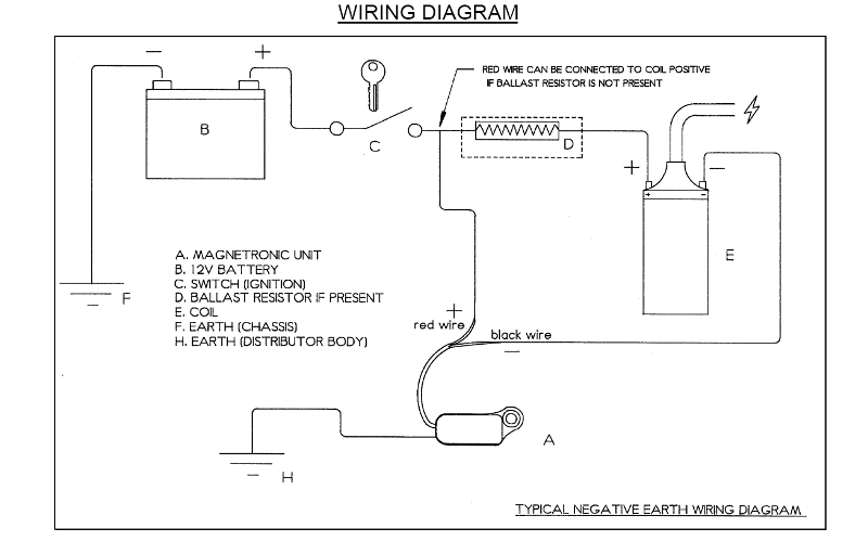
I have a Lumenition MTK-007 unit in the Sprint 44D Distributor and tried to wire it up as per the instruction sheet for a "typical negative earth" supplied by Lumenition.
Image

Evidently I have no spark. Tomorrow I will measure voltage on each wire while cranking and at ignition on at various crank positions.

But it would greatly help if someone could please have a look and describe their setup for me.

[edited for clarity]

Marsu
Swagester
Posts: 570
Joined: 03 Oct 2009 20:57
Location: Australia
Contact:

Postby Marsu » 26 Sep 2010 08:38

Thanks Bruce (Stag76).

That makes more sense now and I'll check it out tomorrow. :-)

Marsu
Swagester
Posts: 570
Joined: 03 Oct 2009 20:57
Location: Australia
Contact:

Postby Marsu » 26 Sep 2010 22:11

Here's the voltages of each wire: Ignition on / Cranking
1. White/Grey - 3.6v / 1.8v
2. White/Blue - 0v / 0v
3. White/Yellow - 12.2v / 10.2
4. White - 12.2v / 10.2

I am totally lost on this, having expected from the information earlier that one of these wires would supply 0v when ignition was on and 12v when cranking.

Or have I misunderstood?

Beans
TRemendous
Posts: 7795
Joined: 15 Mar 2006 19:29
Location: Netherlands
Contact:

Postby Beans » 26 Sep 2010 22:16

Time to start a more methodical approach [:)]
• What year and market is your car;
• Get yourself a wiring diagram for that model;
• Compare the diagram with the loom (unwrap if necessary);

<center>Image
<font color="blue"><i>1980 TR7 DHC (my first car, now restored and back on the road)
1981 TR7 FHC Sprint (better known as 't Kreng)</font id="blue">
<b>[url="http://www.tr7beans.blogspot.com/"]<u><b><font size="2"><font color="red">My Weblog</font id="red"></font id="size2"></b></u>[/url]</b></i></center>

jclay (RIP 2018)
TRemendous
Posts: 6027
Joined: 08 Jul 2006 17:13
Location: USA

Postby jclay (RIP 2018) » 27 Sep 2010 00:30

Get manual from my download site. TR7man.pdf

Clay

[url="http://web.mac.com/jclaythompson/Site/Welcome.html"]My Triumph Site[/url], [url="http://web.mac.com/jclaythompson/iWeb/Technical/Intro.html"]Technical Stuff[/url], [url="http://homepage.mac.com/WebObjects/FileSharing.woa/53/wo/HJMTK8gsojtwKleP.1/0.2.1.2.26.31.97.0.35.0.1.1.1?user=jclaythompson&fpath=Triumph_Articles&templatefn=FileSharing4.html"]Download Page[/url]

Stag76
Swagester
Posts: 691
Joined: 22 Jun 2010 04:14
Location: Australia
Contact:

Postby Stag76 » 27 Sep 2010 03:09

Looking in the book tells me :-
White/Gray - Points Connection/Tach Signal - Attach to Coil -ve.
White/Yellow - Ignition Power - Attach to Ballast Resistor.
White/Blue - Can't find any reference.
White - Can't find any reference.

You can try it without the 0v/12v wire from the starter solenoid. It may be the White/Blue wire and it has been disconnected at the starter solenoid end. There are normally 2 wires (plus the heavy cable) attached to the starter solenoid...a white/red one that switches it, and another wire that carries 12V when the solenoid is closed that supplies the coil to give 12v for a stronger spark for starting, but the lumenition module will probably provide a good enough spark on the lower voltage. If it won't start easily you can add the 0v/12v wire later.

You could wire the lumenition module as shown in your diagram, connect the White/Yellow wire together with the lumenition power (red) to one side of the ballast resistor, and connect the coil positive to the other side of the resistor, then connect the lumenition Black Wire and the White/Gray wire to the coil negative.

TR7 Convertible
Sprint Motor
MegaSquirt EFI

Marsu
Swagester
Posts: 570
Joined: 03 Oct 2009 20:57
Location: Australia
Contact:

Postby Marsu » 01 Oct 2010 01:20

Thanks again Bruce. I have wired as per your last and it sparks nicely (after having to swap out the coil and rotor).

I used the White to supply feed to the Lumention unit and added a new wire from the starter solenoid to coil +ve to give extra current on cranking.

I do have the ROM which usually helps in all maters given it is the only version I have seen with Sprint coverage. Unfortunately, the included wiring diagrams don't cover the variation of the engine harness that must have occurred for the Australian market. (Is this another example of BL having a laugh at future owners?)

JClay, I'm very grateful that you put the ROM online (as I'm sure others are too). BTW, I have run the Adobe Acrobat Pro optical charater recognition (OCR) to convert the version I got from your site. This makes it searchible, and also adjusted some of the page skews and orientation.

I have posted it and others that I converted to my [url="https://docs.google.com/leaf?id=0B3Gv_v1z7nIkMGZjYTBhNTYtMmQ0Ny00YTY1LWJmOTctOGE2NmIzNjM4MjQ2&hl=en"]Google docs[/url]. Feel free to take a copy while it's there.

Marsu
Swagester
Posts: 570
Joined: 03 Oct 2009 20:57
Location: Australia
Contact:

Postby Marsu » 01 Oct 2010 06:16

Update...

I had to disconnect the new cable from starter solenoid to coil +ve as as soon as I changed the ignition switch from start to run the engine would die. So it seems this was a wasted effort in cabling. :-(

But the great thing is that having changed the rotor there IS enough spark to start! I don't really understand this. The rotor is just over 18 months old with no evidence of cracking, fatigue or carbon build up.

But evidently it can no longer transmit HT spark from coil to appropriate contact inside the dissy cap. (I'll measure the lengths of the tips on the working and non-working tomorrow to see if that is the cause.)

Tongue hanging out at present as I've just been for a brief test drive round the block a few times:
[:p][:p][:p][:p][:p]

The 45 DCOEs that I've just fitted as part of this work make a huge difference:
[:D][:D][:D][:D][:D]
---
ps. The DCOEs have changed the exhaust note and smell considerably. I can still taste it now, bringing all sorts of recollections of being at race tracks in the late 70s and early 80s.
[:)][:)][:)][:)][:)]
---
pps. I've just made some adjustments to the Webers and it's even better! I am so amazed at the difference between SUs and DCOEs.

If you own a Sprint I can't recommend this change enough!
[}:)][}:)][}:)][}:)]
FI Spyder
TRemendous
Posts: 8917
Joined: 03 Jul 2006 19:54
Location: Canada

Postby FI Spyder » 01 Oct 2010 16:45

There were/are some bad rotors out there that only last 50 miles or so. One of our club members runs a British car garage and brought both (good and bad)in to meeting for show and tell. They both where brand new but made slightly different. Can't realy recall how to ID them, something with how the metal of rotor is secured to the plastic.


TR7 Spider - 1978 Spifire - 1976 Spitfire - 1988 Tercel 4X4 - Kali on Integra - 1991 Integra
Image

Rich in Vancouver
Swagester
Posts: 781
Joined: 10 Jun 2007 15:20
Location: Canada
Contact:

Postby Rich in Vancouver » 04 Oct 2010 05:16

Apparently on the bad ones the metal bit is riveted in place and the rivet tends to short out on the distributor shaft. The better ones are commonly red in colour and don't have the rivet.

1975 TR7 ACL764U
Image

Post Reply

Who is online

Users browsing this forum: No registered users and 197 guests

cron